Cable Assemblies


Be it from Data Centers to Enterprise Networks, connectorized cables are a necessary and critical component of a robust, physically interconnected fiber optic system, and Sumitomo Electric Lightwave (SEL) has years of experience in supplying these important, highly varied components to facilities worldwide.
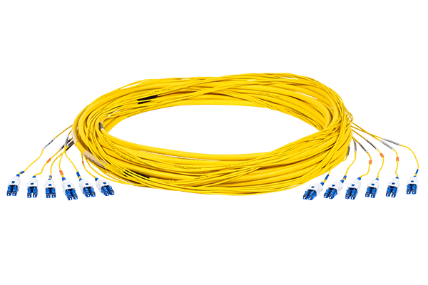
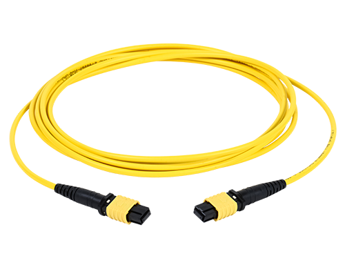
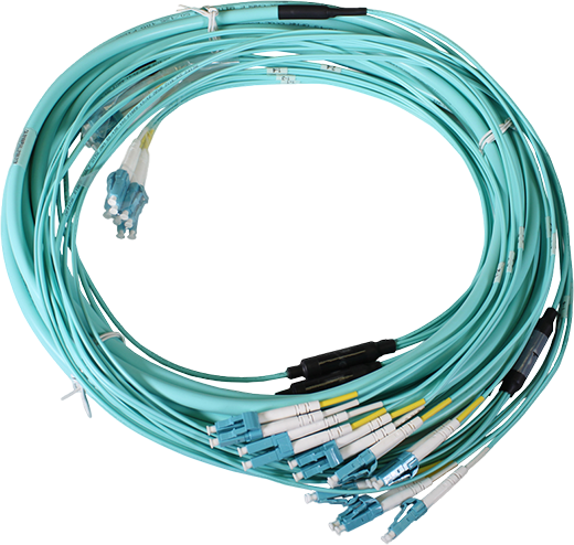
Enhancing SEL’s optical fiber development and manufacturing with a wide range of fiber, cables, connectors and sizes to choose from, SEL can provide most any type of connectorized cable assembly needed at competitive prices and lead times. SEL’s Cable Assemblies are designed for use in any application requiring optical connections. Available in simplex, duplex, interconnect, and trunk configurations, these assemblies can contain up to 864 optical fibers.
Additional fiber count assemblies are available upon request.

Specifications
| Connector Type | Fiber Type | Polish Type | Insertion Loss | Return Loss |
|---|---|---|---|---|
| LC | SM | UPC | ≤ 0.25 dB | ≥ 55 dB |
| SM | APC | ≤ 0.30 dB | ≥ 60 dB | |
| MM | PC | ≤ 0.30 dB | ≥ 25 dB | |
| SC / ST | SM | UPC | ≤ 0.30 dB | ≥ 55 dB |
| SM | APC (SC Only) | ≤ 0.50 dB | ≥ 60 dB | |
| MM | PC | ≤ 0.50 dB | ≥ 25 dB | |
| MPO (Standard) | SM | APC | ≤ 0.75 dB | ≥ 55 dB |
| MM | PC | ≤ 0.60 dB | ≥ 20 dB | |
| MPO (Low Loss) | SM | APC | ≤ 0.35 dB | ≥ 60 dB |
| MM | PC | ≤ 0.35 dB | ≥ 20 dB |
| Property | SMF | MMF OM1 | MMF OM4 | MMF OM5 | |
|---|---|---|---|---|---|
| Polish Type | UPC | APC | UPC | UPC | UPC |
| Housing Color | Blue | Green | Beige | Aqua | Lime |
| Operating Temperature | +14 to +140°F (-10 to +60°C) | ||||
Polarity Diagram
| Multi-Fiber Cable with Single-Fiber Connectors | |
|---|---|
| A – A Connector to A Connector (Crossover Type) | 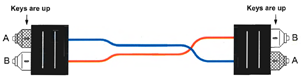 |
| B – A Connector to B Connector (Straight Through Type) | 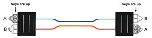 |
Ordering Information (2025)
NEW PART NUMBER CONFIGURATION EFFECTIVE MARCH 2025
We would like to inform you that, as of March 2025, our Cable Assembly part number configuration has been updated. To ensure you have the most accurate and up-to-date information, please refer to the new configuration table available on our website. To help with the transition, we have also kept the old part number configurator available on the product page. This will allow you to cross-reference and smoothly adjust to the new system.
If you have any questions or need further assistance, please contact our Inside Sales team at 800-358-7378.
Instructions: Create a part number by using this character set and codes.
D [ Z ] – [ 1 ] [ 222 ] [ 3 ] [ 4 ] [ 5 ] [ 6 ] [ 7 ] [ 8 ] [999 ] [ U ] – [ X ] [ Y ] [ P ] [ E ]
Part Number ConfiguratorThis user-friendly tool accommodates our most common cable assemblies, making it easy to configure and order the exact product you need. For ordering assistance, please contact our Inside Sales team at 800-358-7378.
| Z – POLARITY/PIN-OUT | 1 – FIBER TYPE | 2 – FIBER COUNT (3-DIGITS) | 3 – CABLE DESIGN | 4 – ARMOR TYPE | 5 – CABLE JACKET/FLAME RETARDANCY RATING |
|---|---|---|---|---|---|
| Single Fiber Cable A – Single Fiber Cable Multi-Fiber Cable with Single-Fiber Connectors (LC, SC, ST, etc.) A – A Connector to A Connector (Crossover Type; See Polarity Diagram) B – A Connector to B Connector (Straight Through Type; See Polarity Diagram) Multi-Fiber Cable with Multi-Fiber Connectors (MPO, MTP, etc.) A – MPO/MTP Type A B – MPO/MTP Type B C – MPO/MTP Type C D – MPO/MTP SM Type B (With Window Up Key Down) G – 40G/400G Type B (Outer 8F out of 12F) H – 40G/400G Type A (Outer 8F out of 12F) 1 – MPO24/MTP24 Config 1 2 – MPO24/MTP24 Config 2 3 – MPO24/MTP24 Config 3 4 – MPO24/MTP24 Config 4 | 1 – OM1 (62.5 μm) 2 – OM2 (50 μm) 3 – OM3 (50 μm) 4 – OM4 (50 μm) 5 – OM5 (50 μm) 8 – SM (G.657.A2) 9 – SM (G.657.A1) | 001 – 1f 002 – 2f 004 – 4f 006 – 6f 008 – 8f 012 – 12f 016 – 16f 024 – 24f 036 – 36f 048 – 48f 050 – 50f 060 – 60f 072 – 72f 096 – 96f 144 – 144f 192 – 192f 288 – 288f 432 – 432f 576 – 576f 864 – 864f | P – Pliable Ribbon (250μm) Q – Pliable Ribbon (200μm) A – Flat Ribbon (250μm) B – Flat Ribbon (200μm) X – Loose Buffer (200μm) Y – Loose Buffer (250μm) Z – Tight Buffer (900μm) | N – No Armor L – Interlocking Armor M – Micro Armor | A – OSP B – Riser C – Indoor/Outdoor Riser D – LSZH (Low Smoke Zero Halogen) E – Riser LSZH F – Indoor/Outdoor Riser LSZH G – Plenum H – Indoor/Outdoor Plenum 2 – B1ca 3 – B2ca 4 – Cca 5 – Dca |
| 6 – SUBUNITS (FURCATION CORD) | 7 – CONNECTOR END A | 8 – CONNECTOR END B | 9 – LENGTH (3-DIGITS) | U – LENGTH UNIT |
|---|---|---|---|---|
| C – 1.6 mm T – 2.0 mm X – 3.0 mm 9 – 900 μm V – SEL Option D – Not Applicable | 0 – LC, Simplex 1 – LC, Duplex (Zip Cord) 2 – LC/APC, Simplex 3 – LC/APC, Duplex 4 – LC-UNIBOOT (Non-Reversible, No Pull Tab/Boot) 5 – LC-UNIBOOT (Reversible, No Pull Tab/Boot) 6 – LC-UNIBOOT (Reversible, w/ Pull Tab/Boot) 7 – LC-UNIBOOT/APC (Non-Reversible, No Pull Tab/Boot) 8 – LC-UNIBOOT/APC (Reversible, No Pull Tab/Boot) 9 – LC-UNIBOOT/APC (Reversible, w/ Pull Tab/Boot) A – MPO/MTP (Male/Pinned), 8 Fiber, Low Loss B – MPO/MTP (Male/Pinned), 8 Fiber, Std Loss C – MPO/MTP (Female/Unpinned), 8 Fiber, Low Loss D – MPO/MTP (Female/Unpinned), 8 Fiber, Std Loss E – MPO/MTP (Male/Pinned), 12 Fiber, Low Loss F – MPO/MTP (Male/Pinned), 12 Fiber, Std Loss G – MPO/MTP (Female/Unpinned), 12 Fiber, Low Loss H – MPO/MTP (Female/Unpinned), 12 Fiber, Std Loss J – MPO/MTP (Male/Pinned), 16 Fiber, Low Loss K – MPO/MTP (Male/Pinned), 16 Fiber, Std Loss L – MPO/MTP (Female/Unpinned), 16 Fiber, Low Loss M – MPO/MTP (Female/Unpinned), 16 Fiber, Std Loss N – MPO/MTP (Male/Pinned), 24 Fiber, Low Loss P – MPO/MTP (Male/Pinned), 24 Fiber, Std Loss Q – MPO/MTP (Female/Unpinned), 24 Fiber, Low Loss R – MPO/MTP (Female/Unpinned), 24 Fiber, Std Loss S – SC, Duplex (Zip Cord) T – SC, Simplex U – SC/APC, Duplex (Zip Cord) V – SC/APC, Simplex W – ST X – BARE END (Open/Blunt) Y – FC Z – FC/APC | 0 – LC, Simplex 1 – LC, Duplex (Zip Cord) 2 – LC/APC, Simplex 3 – LC/APC, Duplex 4 – LC-UNIBOOT (Non-Reversible, No Pull Tab/Boot) 5 – LC-UNIBOOT (Reversible, No Pull Tab/Boot) 6 – LC-UNIBOOT (Reversible, w/ Pull Tab/Boot) 7 – LC-UNIBOOT/APC (Non-Reversible, No Pull Tab/Boot) 8 – LC-UNIBOOT/APC (Reversible, No Pull Tab/Boot) 9 – LC-UNIBOOT/APC (Reversible, w/ Pull Tab/Boot) A – MPO/MTP (Male/Pinned), 8 Fiber, Low Loss B – MPO/MTP (Male/Pinned), 8 Fiber, Std Loss C – MPO/MTP (Female/Unpinned), 8 Fiber, Low Loss D – MPO/MTP (Female/Unpinned), 8 Fiber, Std Loss E – MPO/MTP (Male/Pinned), 12 Fiber, Low Loss F – MPO/MTP (Male/Pinned), 12 Fiber, Std Loss G – MPO/MTP (Female/Unpinned), 12 Fiber, Low Loss H – MPO/MTP (Female/Unpinned), 12 Fiber, Std Loss J – MPO/MTP (Male/Pinned), 16 Fiber, Low Loss K – MPO/MTP (Male/Pinned), 16 Fiber, Std Loss L – MPO/MTP (Female/Unpinned), 16 Fiber, Low Loss M – MPO/MTP (Female/Unpinned), 16 Fiber, Std Loss N – MPO/MTP (Male/Pinned), 24 Fiber, Low Loss P – MPO/MTP (Male/Pinned), 24 Fiber, Std Loss Q – MPO/MTP (Female/Unpinned), 24 Fiber, Low Loss R – MPO/MTP (Female/Unpinned), 24 Fiber, Std Loss S – SC, Duplex (Zip Cord) T – SC, Simplex U – SC/APC, Duplex (Zip Cord) V – SC/APC, Simplex W – ST X – BARE END (Open/Blunt) Y – FC Z – FC/APC | 001 – 001-999+ | F – Feet M – Meters I – Inch |
| X – END A BREAKOUT LENGTH | Y – END B BREAKOUT LENGTH | P – PULLING EYE | E – FOR EXACT LENGTH ONLY |
|---|---|---|---|
| 1 – 18 in (457 mm) – No Stagger 2 – 24 in (609 mm) – No Stagger 3 – 36 in (914 mm) – No Stagger 4 – 48 in (1,219 mm) – No Stagger 5 – 60 in (1,524 mm) – No Stagger 6 – 72 in (1,828 mm) – No Stagger 7 – 16 in (406 mm) – No Stagger 8 – 12 in (305 mm) – No Stagger A – 18 in (457 mm) – Subunit Stagger B – 24 in (609 mm) – Subunit Stagger C – 36 in (914 mm) – Subunit Stagger D – 48 in (1,219 mm) – Subunit Stagger E – 60 in (1,524 mm) – Subunit Stagger F – 72 in (1,828 mm) – Subunit Stagger H – 18 in (457 mm) – Fiber Pair Stagger J – 24 in (609 mm) – Fiber Pair Stagger K – 36 in (914 mm) – Fiber Pair Stagger L – 48 in (1,219 mm) – Fiber Pair Stagger M – 60 in (1,524 mm) – Fiber Pair Stagger N – 72 in (1,828 mm) – Fiber Pair Stagger Q – 18 in (457 mm) – Subunit and Fiber Pair Stagger R – 24 in (609 mm) – Subunit and Fiber Pair Stagger S – 36 in (914 mm) – Subunit and Fiber Pair Stagger T – 48 in (1,219 mm) – Subunit and Fiber Pair Stagger U – 60 in (1,524 mm) – Subunit and Fiber Pair Stagger V – 72 in (1,828 mm) – Subunit and Fiber Pair Stagger W – Special X – No Breakout | 1 – 18 in (457 mm) – No Stagger 2 – 24 in (609 mm) – No Stagger 3 – 36 in (914 mm) – No Stagger 4 – 48 in (1,219 mm) – No Stagger 5 – 60 in (1,524 mm) – No Stagger 6 – 72 in (1,828 mm) – No Stagger 7 – 16 in (406 mm) – No Stagger 8 – 12 in (305 mm) – No Stagger A – 18 in (457 mm) – Subunit Stagger B – 24 in (609 mm) – Subunit Stagger C – 36 in (914 mm) – Subunit Stagger D – 48 in (1,219 mm) – Subunit Stagger E – 60 in (1,524 mm) – Subunit Stagger F – 72 in (1,828 mm) – Subunit Stagger H – 18 in (457 mm) – Fiber Pair Stagger J – 24 in (609 mm) – Fiber Pair Stagger K – 36 in (914 mm) – Fiber Pair Stagger L – 48 in (1,219 mm) – Fiber Pair Stagger M – 60 in (1,524 mm) – Fiber Pair Stagger N – 72 in (1,828 mm) – Fiber Pair Stagger Q – 18 in (457 mm) – Subunit and Fiber Pair Stagger R – 24 in (609 mm) – Subunit and Fiber Pair Stagger S – 36 in (914 mm) – Subunit and Fiber Pair Stagger T – 48 in (1,219 mm) – Subunit and Fiber Pair Stagger U – 60 in (1,524 mm) – Subunit and Fiber Pair Stagger V – 72 in (1,828 mm) – Subunit and Fiber Pair Stagger W – Special X – No Breakout | A – Pulling Eye on End A Only B – Pulling Eye on End B Only D – Pulling Eye on Both End X – No Pulling Eye | E – Exact Length, +/- 0.5 inches X – NOT Exact Length |
Cable Assembly, A Connector to B Connector (Crossover Type), SM (G.657.A1), 2-Fibers, Tight Buffer (900 μm), No Armor, Riser, 2.0 mm Subunit, LC-Duplex to LC-Duplex, 3 Meters Long, No Breakout, No Pulling Eye, Not Exact Length
Ordering Information (2024)
NEW PART NUMBER CONFIGURATION EFFECTIVE MARCH 2025
We would like to inform you that, as of March 2025, our Cable Assembly part number configuration has been updated. To ensure you have the most accurate and up-to-date information, please refer to the new configuration table available on our website. To help with the transition, we have also kept the old part number configurator available on the product page. This will allow you to cross-reference and smoothly adjust to the new system.
If you have any questions or need further assistance, please contact our Inside Sales team at 800-358-7378.
Instructions: Create a part number by using this character set and codes.
C [ Z ] – [ 1 ] [ 222 ] [ 3 ] [ 4 ] [ 5 ] [ 6 ] [ 7 ] [ 8 ] [999 ] [ U ] – [ X ] [ Y ] [ P ]
Part Number ConfiguratorThis user-friendly tool accommodates our most common cable assemblies, making it easy to configure and order the exact product you need. For ordering assistance, please contact our Inside Sales team at 800-358-7378.
| Z – POLARITY/PIN-OUT | 1 – FIBER TYPE | 2 – FIBER COUNT (3-DIGITS) | 3 – CABLE DESIGN | 4 – ARMOR TYPE | 5 – CABLE JACKET/FLAME RETARDANCY RATING |
|---|---|---|---|---|---|
| Single Fiber Cable A – Single Fiber Cable Multi-Fiber Cable with Single-Fiber Connectors (LC, SC, ST, etc.) A – A Connector to A Connector (Crossover Type; See Polarity Diagram) B – A Connector to B Connector (Straight Through Type; See Polarity Diagram) Multi-Fiber Cable with Multi-Fiber Connectors (MPO, MTP, etc.) A – MPO/MTP Type A B – MPO/MTP Type B C – MPO/MTP Type C D – MPO/MTP SM Type B (With Window Up Key Down) G – 40G/400G Type B (Outer 8F out of 12F) H – 40G/400G Type A (Outer 8F out of 12F) 1 – MPO24/MTP24 Config 1 2 – MPO24/MTP24 Config 2 3 – MPO24/MTP24 Config 3 4 – MPO24/MTP24 Config 4 | 1 – OM1 (62.5 μm) 2 – OM2 (50 μm) 3 – OM3 (50 μm) 4 – OM4 (50 μm) 5 – OM5 (50 μm) 8 – SM (G.657.A2) 9 – SM (G.657.A1) | 001 – 1f 002 – 2f 004 – 4f 006 – 6f 008 – 8f 012 – 12f 016 – 16f 024 – 24f 036 – 36f 048 – 48f 050 – 50f 060 – 60f 072 – 72f 096 – 96f 144 – 144f 288 – 288f 432 – 432f 576 – 576f 864 – 864f | P – Pliable Ribbon (250μm) Q – Pliable Ribbon (200μm) A – Flat Ribbon (250μm) B – Flat Ribbon (200μm) X – Loose Buffer (200μm) Y – Loose Buffer (250μm) Z – Tight Buffer (900μm) | N – No Armor L – Interlocking Armor M – Micro Armor | A – OSP B – Riser C – Indoor/Outdoor Riser D – LSZH (Low Smoke Zero Halogen) E – Riser LSZH F – Indoor/Outdoor Riser LSZH G – Plenum H – Indoor/Outdoor Plenum 2 – B1ca 3 – B2ca 4 – Cca 5 – Dca |
| 6 – SUBUNITS (FURCATION CORD) | 7 – CONNECTOR END A | 8 – CONNECTOR END B | 9 – LENGTH (3-DIGITS) | U – LENGTH UNIT |
|---|---|---|---|---|
| C – 1.6 mm T – 2.0 mm X – 3.0 mm 9 – 900 μm V – SEL Option D – Not Applicable | 5 – MPO (Male/Pinned), 12 Fiber, Low Loss 6 – MPO (Male/Pinned), 12 Fiber, Std Loss 7 – MPO (Female/Unpinned), 12 Fiber, Low Loss 8 – MPO (Female/Unpinned), 12 Fiber, Std Loss 0 – MPO (Female/Unpinned), 24 Fiber, Low Loss W – MPO (Female/Unpinned), 24 Fiber, Std Loss 9 – MPO (Male/Pinned), 24 Fiber, Low Loss Z – MPO (Male/Pinned), 24 Fiber, Std Loss 1 – MTP (Male/Pinned), 12 Fiber, Low Loss M – MTP (Male/Pinned), 12 Fiber, Std Loss 2 – MTP (Female/Unpinned), 12 Fiber, Low Loss Y – MTP (Female/Unpinned), 12 Fiber, Std Loss 4 – MTP (Male/Pinned), 24 Fiber, Low Loss P – MTP (Male/Pinned), 24 Fiber, Std Loss 3 – MTP (Female/Unpinned), 24 Fiber, Low Loss N – MTP(Female/Unpinned), 24 Fiber, Std Loss L – LC, MM/SM, DX Q – LC, MM/SM, SX A – LC/APC, DX E – LC/APC, SX R – LC-UNIBOOT (Reversible/No Pull Tab) G – LC-UNIBOOT (Reversible w/ Pull Tab) S – SC, MM/SM, DX V – SC, MM/SM, SX B – SC/APC, DX H – SC/APC, SX F – FC, MM/SM C – FC/APC T – ST, MM/SM X – BARE END (Open/Blunt) | 5 – MPO (Male/Pinned), 12 Fiber, Low Loss 6 – MPO (Male/Pinned), 12 Fiber, Std Loss 7 – MPO (Female/Unpinned), 12 Fiber, Low Loss 8 – MPO (Female/Unpinned), 12 Fiber, Std Loss 0 – MPO (Female/Unpinned), 24 Fiber, Low Loss W – MPO (Female/Unpinned), 24 Fiber, Std Loss 9 – MPO (Male/Pinned), 24 Fiber, Low Loss Z – MPO (Male/Pinned), 24 Fiber, Std Loss 1 – MTP (Male/Pinned), 12 Fiber, Low Loss M – MTP (Male/Pinned), 12 Fiber, Std Loss 2 – MTP (Female/Unpinned), 12 Fiber, Low Loss Y – MTP (Female/Unpinned), 12 Fiber, Std Loss 4 – MTP (Male/Pinned), 24 Fiber, Low Loss P – MTP (Male/Pinned), 24 Fiber, Std Loss 3 – MTP (Female/Unpinned), 24 Fiber, Low Loss N – MTP(Female/Unpinned), 24 Fiber, Std Loss L – LC, MM/SM, DX Q – LC, MM/SM, SX A – LC/APC, DX E – LC/APC, SX R – LC-UNIBOOT (Reversible/No Pull Tab) G – LC-UNIBOOT (Reversible w/ Pull Tab) S – SC, MM/SM, DX V – SC, MM/SM, SX B – SC/APC, DX H – SC/APC, SX F – FC, MM/SM C – FC/APC T – ST, MM/SM X – BARE END (Open/Blunt) | 001 – 001-999+ | F – Feet M – Meters I – Inch |
| X – END A BREAKOUT LENGTH | Y – END B BREAKOUT LENGTH | P – PULLING EYE | E0.5 – FOR EXACT LENGTH ONLY |
|---|---|---|---|
| 1 – 18 in (457 mm) – No Stagger 2 – 24 in (609 mm) – No Stagger 3 – 36 in (914 mm) – No Stagger 4 – 48 in (1,219 mm) – No Stagger 5 – 60 in (1,524 mm) – No Stagger 6 – 72 in (1,828 mm) – No Stagger 7 – 16 in (406 mm) – No Stagger 8 – 12 in (305 mm) – No Stagger A – 18 in (457 mm) – Subunit Stagger B – 24 in (609 mm) -Subunit Stagger C – 36 in (914 mm) -Subunit Stagger D – 48 in (1,219 mm) -Subunit Stagger E – 60 in (1,524 mm) -Subunit Stagger F – 72 in (1,828 mm) -Subunit Stagger H – 18 in (457 mm) -Fiber Pair Stagger J – 24 in (609 mm) -Fiber Pair Stagger K – 36 in (914 mm) -Fiber Pair Stagger L – 48 in (1,219 mm) -Fiber Pair Stagger M – 60 in (1,524 mm) -Fiber Pair Stagger N – 72 in (1,828 mm) -Fiber Pair Stagger Q – 18 in (457 mm) -Subunit & Fiber Pair Stagger R – 24 in (609 mm) -Subunit & Fiber Pair Stagger S – 36 in (914 mm) -Subunit & Fiber Pair Stagger T – 48 in (1,219 mm) -Subunit & Fiber Pair Stagger U – 60 in (1,524 mm) – Subunit & Fiber Pair Stagger V – 72 in (1,828 mm) -Subunit & Fiber Pair Stagger X – No Breakout | 1 – 18 in (457 mm) – No Stagger 2 – 24 in (609 mm) – No Stagger 3 – 36 in (914 mm) – No Stagger 4 – 48 in (1,219 mm) – No Stagger 5 – 60 in (1,524 mm) – No Stagger 6 – 72 in (1,828 mm) – No Stagger 7 – 16 in (406 mm) – No Stagger 8 – 12 in (305 mm) – No Stagger A – 18 in (457 mm) – Subunit Stagger B – 24 in (609 mm) -Subunit Stagger C – 36 in (914 mm) -Subunit Stagger D – 48 in (1,219 mm) -Subunit Stagger E – 60 in (1,524 mm) -Subunit Stagger F – 72 in (1,828 mm) -Subunit Stagger H – 18 in (457 mm) -Fiber Pair Stagger J – 24 in (609 mm) -Fiber Pair Stagger K – 36 in (914 mm) -Fiber Pair Stagger L – 48 in (1,219 mm) -Fiber Pair Stagger M – 60 in (1,524 mm) -Fiber Pair Stagger N – 72 in (1,828 mm) -Fiber Pair Stagger Q – 18 in (457 mm) -Subunit & Fiber Pair Stagger R – 24 in (609 mm) -Subunit & Fiber Pair Stagger S – 36 in (914 mm) -Subunit & Fiber Pair Stagger T – 48 in (1,219 mm) -Subunit & Fiber Pair Stagger U – 60 in (1,524 mm) – Subunit & Fiber Pair Stagger V – 72 in (1,828 mm) -Subunit & Fiber Pair Stagger X – No Breakout | A – Pulling Eye on End A Only B – Pulling Eye on End B Only D – Pulling Eye on Both End X – No Pulling Eye | E0.5 – Exact Length,+/- 0.5 inches |
Cable Assembly, Method A, SM, 144F, Pliable Ribbon, No Armor, Plenum, 900μm Furcation, LC/D to LC/D, 250 Feet Long, 36 inch Breakout Each End, Pulling Eye
Features
- Industry Standard Connector Configurations: Compatible with all industry-standard connector configurations for maximum flexibility.
- Custom Termination & Cable Options: Tailor configurations to meet specific networking needs.
- Multiple Connector End Configurations: Various end configurations available. See ordering information on pages 4-5.
- Compatible Fiber Types: Can be designed with the following fiber types for versatility: OM1 (62.5μm); OM2, OM3, OM4, OM5 (50μm); SM (G.657.A2, G.657.A1)
- Environmental Suitability: Riser, plenum, and LSZH jackets provide options for different environmental and safety requirements.
- 12f/8f MPO Ribbon Assemblies: Quick and easy termination for 1G, 10G, 40G, and 100G applications.
- Flexible MPO Connector: Allows for gender and polarity changes in the field and push-pull operations.
- Superior Insertion Loss & Back Reflection Performance: Ensures minimal signal loss and high-quality data transmission.
- 100% Visual/Performance Verification: Rigorous visual and optical testing ensures optimal performance.
- Standards Compliance: Exceeds TIA and Telcordia requirements for quality and reliability.