December 21, 2023
A Move to Overhead Trays
Over the last several decades, cable management, routing cross connects, backbone, or trunk cables through a DC facility, has gradually migrated from utilizing the space under raised flooring to creating new pathways via overhead suspended trays. Spurred on by massive increases in hardware and cables needed to provide the bandwidth to store and process the data within modern hyperscale data centers, these once convenient underfloor pathways became a liability as constriction steadily decreased subfloor air flow and increased overall ambient temperature. However, whereas raised floor pathways offered a large area to place cables and flexibility in the form of the number and weight of the cables placed, overhead trays are limited. They must abide by tray capacity standards, meaning that the cable diameter and weight for the fiber count is now of the utmost importance.
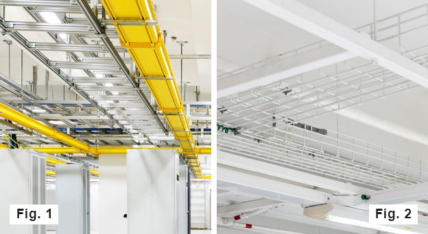
Suspended cable trays are a common method of routing wire and cable. Figure 1: Shows examples of ladder and solid bottom trays. Figure 2: Shows an example of a basket tray
What do the Standards Say?
National Electrical Code (NFPA 70) Article 392 – Cable Tray Standard states: “the sum of the area of all cables at any cross section shall not exceed 50 percent of the interior cross-sectional area of the cable tray.”
The Telecommunications Industry Association (TIA- 942) Telecommunications Infrastructure Standard for Data Centers limits cable tray capacity to 40 percent.
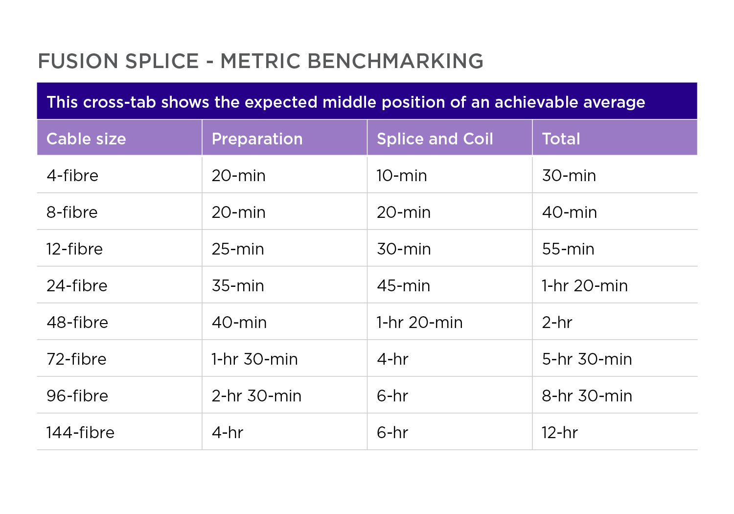
Tray Densities by Fiber Count
Considering the above standards and the trend towards ever-increasing bandwidth needs in the DC, trunk or cross-connect cables reaching from 288 – 1728-F within the DC with small counts used to connect specific areas are not uncommon. Assuming that weight limits are met throughout the examples, the numbers below offer insight into the densities possible within a single overhead tray.
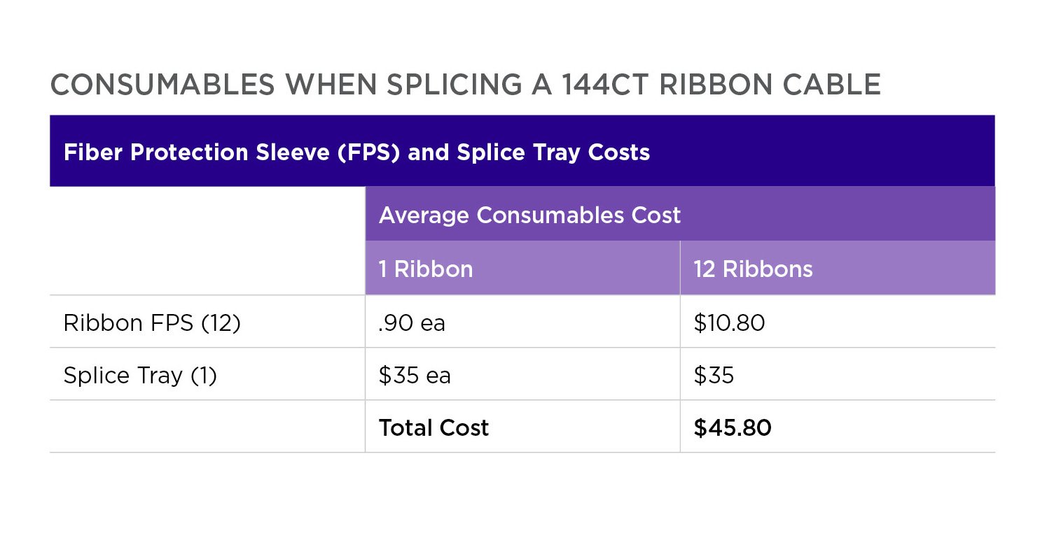
For all examples above we have solved for a 4-inch-deep, 24-inch-wide tray offering 96 square inches of cable pathway with a 50-percent fill rate as its maximum. Additionally, we will assume the use of Sumitomo Electric Lightwave’s (SEL) Freeform Ribbon® Indoor Central Tube 250 μm cables.
Using these results as a guide, DC managers can now focus on network flexibility, future readiness, lifetime ease of use, security, and overall cost (installation and product cost) when finalizing infrastructure designs.
For more information on products and network design questions, contact a Sumitomo Electric Lightwave expert.
Tag(s):